VADTel-IIoTU ValveLink
VADTel-IIoTu-ValveLink is a DIN-rail controller for remote valve control and cabinet-level telemetry in utility metering installations. It combines cellular communication, isolated RS-485 acquisition from compatible external metering devices, cabinet tamper supervision, actuator position interfacing and dedicated outputs for pneumatic-manifold and compressor control.
Key Platform Fit
The unit covers four core functions in a single cabinet-level device: cellular telemetry, isolated RS-485 data acquisition, valve actuator control and cabinet supervision.
Core Capabilities
Valve Control
Dedicated outputs for pneumatic-manifold control and compressor actuation. The unit drives compressor and pneumatic manifold equipment according to project logic, ensuring reliable remote shutoff capability for gas, water and heat applications.
Metering-Node Integration
Collects live values, archives, configuration data and events from compatible RS-485 meters. The controller polls external gas volume correctors, water meters, heat calculators and other RS-485 field devices, consolidating telemetry at the cabinet level.
Cabinet Supervision
Supports cabinet tamper input and actuator stem-position monitoring. A dedicated dry-contact tamper input detects unauthorized cabinet access, while 3-wire position sensing tracks actuator state in real time.
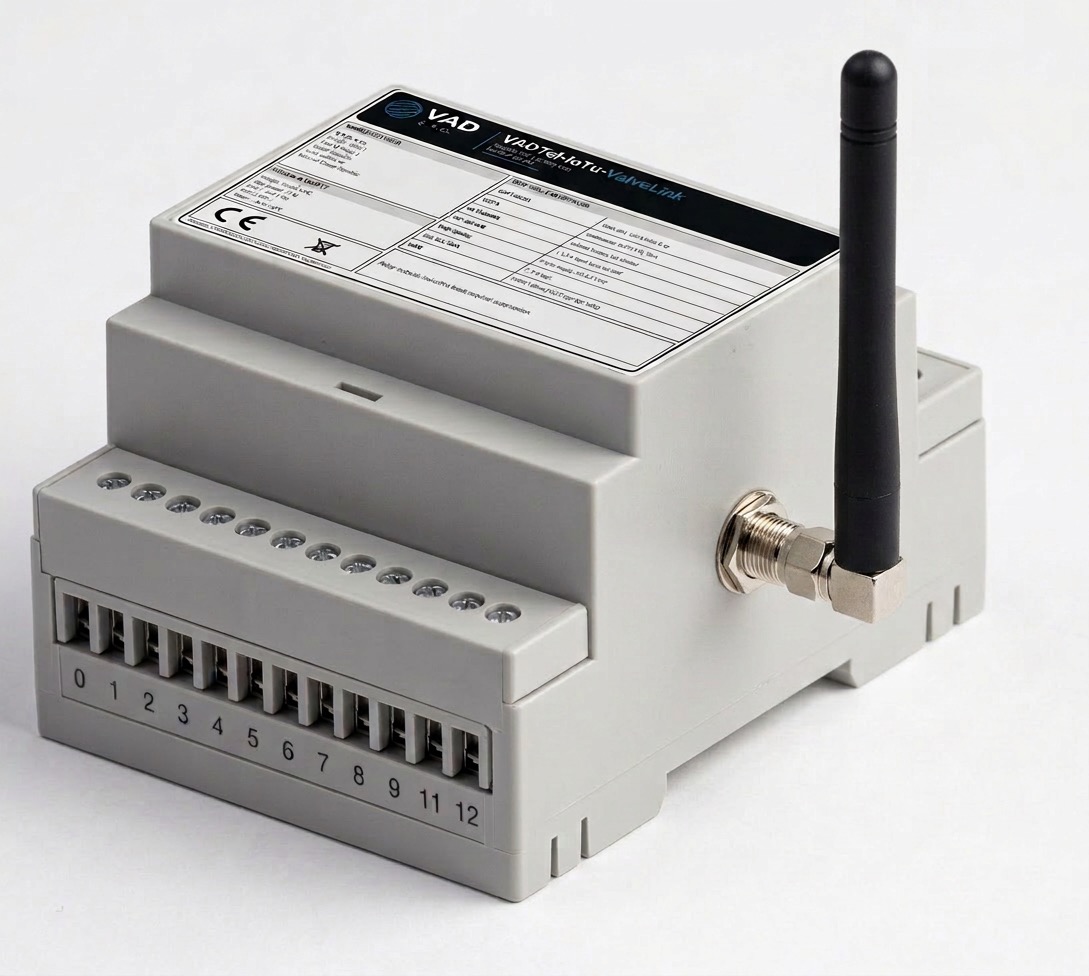
Field-Ready Form Factor
DIN-rail enclosure with 12–24 V DC supply and an operating temperature range of -40 to +60 °C, designed for year-round outdoor cabinet deployment.
Typical Applications
The controller serves utility metering installations where remote valve control and telemetry are required:
- Gas metering nodes with remote shutoff — gas volume correctors and cabinet telemetry
- Water distribution chambers with automated valves and compatible RS-485 metering
- District-heating substations — heat calculators, valve stations and cabinet-level telemetry
- Remote valve stations requiring centralized supervisory control
Operating Role
VADTel-IIoTu-ValveLink acts as the cabinet-level node between the local valve assembly, metering devices and the supervisory backend. It polls compatible meters over RS-485, supervises cabinet-level status and reports telemetry through GPRS or NB-IoT communication.
Technical Specifications
Power and Safety
| Parameter | Value |
|---|---|
| Mounting | DIN rail, cabinet installation |
| Supply voltage | 12–24 V DC |
| Maximum power consumption | 15 W max |
| Internal circuits | SELV < 30 V DC |
| Overvoltage category | OVC II |
| Pollution degree | 2 |
| Operating temperature | -40…+60 °C |
Control Outputs
| Output | Rating |
|---|---|
| OUT1–OUT3 | 3 outputs, 12/24 V DC, 5 A max each |
| OUT4 | 1 output, 12/24 V DC, 10 A max |
| Inductive loads | External suppression required |
Inputs and Local Interfaces
| Interface | Specification |
|---|---|
| IN-TAMPER | Dry contact, 1 input |
| POS-SENSE | 3-wire, 3.0–4.2 V DC |
| I²C | 3.3 V logic |
Communications
| Interface | Specification |
|---|---|
| Cellular | GPRS / NB-IoT (LTE Cat-NB1 / NB2) |
| RS-485 | 1 isolated port, A/B |
| RS-485 signal level | 1.5–5 V differential |
| Metering scope | Compatible external meters, correctors, calculators |
Standard Product Variant
| Field | Value |
|---|---|
| Model | VADTel-IIoTu-ValveLink |
| Standard P/N | VAD-IIOTU-VLK-01 |
| Form factor | DIN-rail controller |
Typical Control and Telemetry Workflow
The unit operates in a four-stage cycle within each polling interval:
1. Poll meters — Read current values, archives and events from compatible RS-485 devices.
2. Monitor local state — Supervise cabinet tamper, actuator position and cabinet-level status.
3. Control valve equipment — Drive compressor and pneumatic manifold according to project logic.
4. Report telemetry — Send telemetry and event data through cellular communication to the supervisory system.
Typical Connected Subsystems
The controller manages the following cabinet-level subsystems: 12/24 V supply or battery-backed cabinet power, GSM antenna, cabinet tamper switch, compressor, pneumatic manifold, actuator position board, pneumatic actuator, and compatible external meters, correctors or calculators on RS-485.
Installation and Safety Notes
Installation Precautions
- Install in a protected control cabinet
- Route power, antenna and RS-485 according to EMC practice
- Verify compressor and actuator current against output ratings before commissioning
- Use external suppression with inductive loads
- Standard product version is intended for non-Ex cabinet installation
Integration Notes
Pressure-sensor implementation is project-specific. Output protection and suppression depend on the selected load. Final terminal assignment follows project wiring documentation.
System Integrator Checklist
Before commissioning, confirm the following items:
- Actuator safe state and shutdown philosophy
- Compatible meter protocol map for the selected project
- Protective devices, cabinet design and field wiring
- Antenna placement and cellular service availability
EU Documentation and Market Release
Product labeling and EU Declaration of Conformity apply to the supplied market variant. Refer to project documentation for final terminal map and installation instructions. WEEE disposal and product traceability follow the supplied label set.
Application Limit
VADTel-IIoTu-ValveLink is a cabinet-level controller and telemetry unit. It is not a stand-alone gas safety shutoff device; final compliance of the complete installation remains with the system integrator.
IIoT Ecosystem
Cloud-based supervisory platform for valve control, device monitoring and service management.
The IIoT Ecosystem platform provides a unified supervisory interface for every deployed VADTel-IIoTu-ValveLink unit. Operators see current valve status, the last issued command and the latest communication timestamp at a glance.
Management Log
A full audit trail of valve state changes is maintained, recording each open/close event with its timestamp, result and origin — whether triggered from the server, a local control panel or an automated rule.
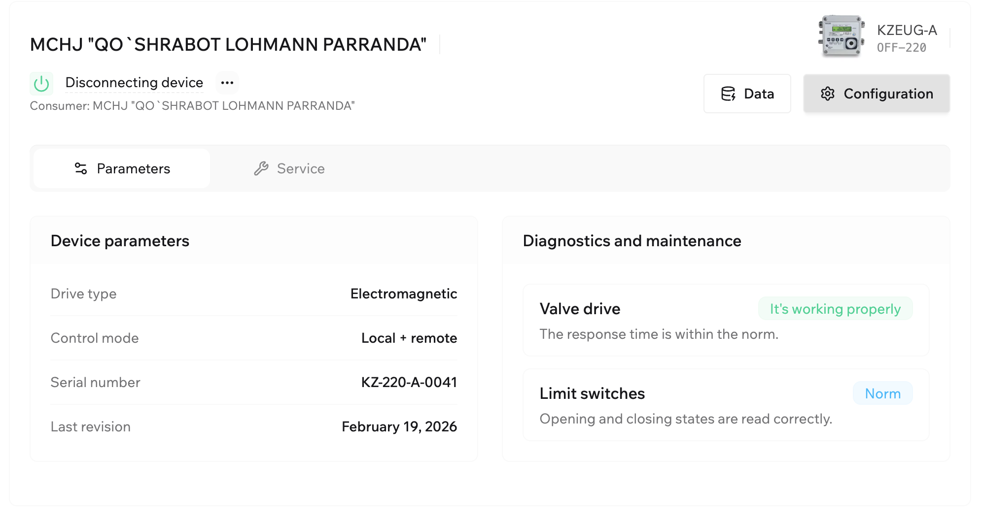
Device Parameters and Diagnostics
The platform stores key device parameters — drive type, control mode, serial number, last revision date — alongside real-time diagnostics. Valve drive health, limit switch status and response time are monitored continuously, with alerts raised when values fall outside the norm.
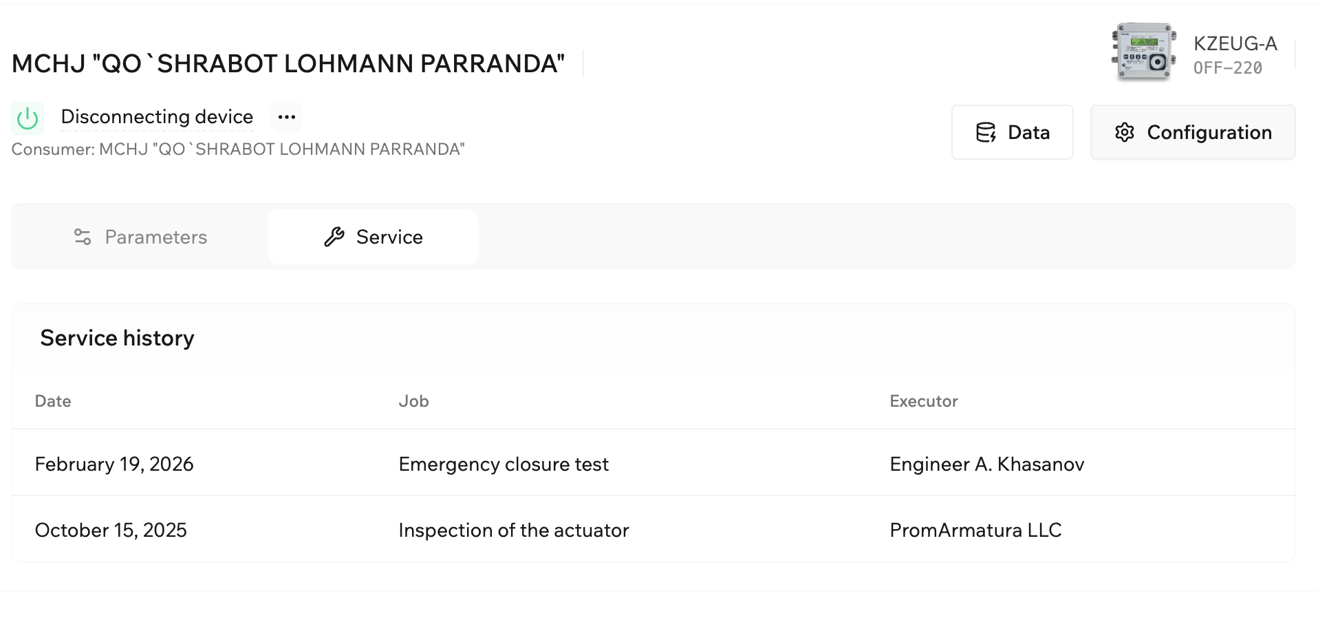
Service History
Every maintenance event is logged with its date, job description and executor, giving operations teams a complete lifecycle record for each unit.
Platform Capabilities
- Remote valve control (open / close) through cellular communication
- Real-time device status monitoring and communication session tracking
- Management log with full audit trail of valve state changes
- Device diagnostics: valve drive health, limit switch status, response time
- Service history with maintenance records, job types and executor tracking
Doc ID: VAD-IIOTU-VLK-DS-EN | Rev. 1.0 | Date: 2026-04-15 | support@vadsro.eu | iot.vadsro.eu